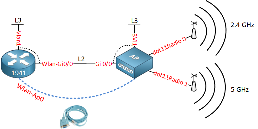
The Cisco 1941W router has wireless onboard but this isn’t just any
ordinary “wireless” interface. It’s a complete access point that has to
be configured separately from the router. The router
and (virtual) access point are connected to each other by using a
virtual gigabit interface. Let me give you a picture to help you
visualize how this works internally:

All the interfaces are above are not real but virtual interfaces on the router. Let me explain each interface to you:
Each VLAN will need an IP address that can be used as the default gateway for its wireless clients, that’s why we need to create VLAN interfaces on the router.
In the next part of this tutorial i’ll give you a configuration example where we will create a wireless network and two VLANs:

Let me explain this picture:
First we will configure a DHCP pool for the wireless users:
Next step is to make sure the Wlan-Gi0/0 interface is operational:
Now we’ll configure the BVI interface for management traffic:
First we will create a simple wireless network that uses a pre-shared key for WPA:
All the interfaces are above are not real but virtual interfaces on the router. Let me explain each interface to you:
- The router has a Wlan-AP0 interface which is only used to access the console of the access point.
- The access point has a dot11Radio 0 interface which is the radio for the 2.4GHz frequency.
- The access point also has a dot11Radio 1 interface which is the radio for the 5GHz frequency.
- The access point has a Gi0/0 interface which is connected to the Wlan-Gi0/0 on the router.
- The Wlan-Gi0/0 on the router and the Gi 0/0 interface on the access point are layer 2 interfaces (switchport) that we can use as a trunk.
- The Vlan1 interface on the router is a routed port where you can configure an IP addres. It’s connected to the Wlan-Gi0/0 interface so that’s why you see the dashed line.
- The BVI1 interface on the access point is similar to the Vlan1 interface of the router. It’s connected to the Gi0/0 interface.
Each VLAN will need an IP address that can be used as the default gateway for its wireless clients, that’s why we need to create VLAN interfaces on the router.
In the next part of this tutorial i’ll give you a configuration example where we will create a wireless network and two VLANs:
- One VLAN for wireless users.
- One VLAN for management traffic.
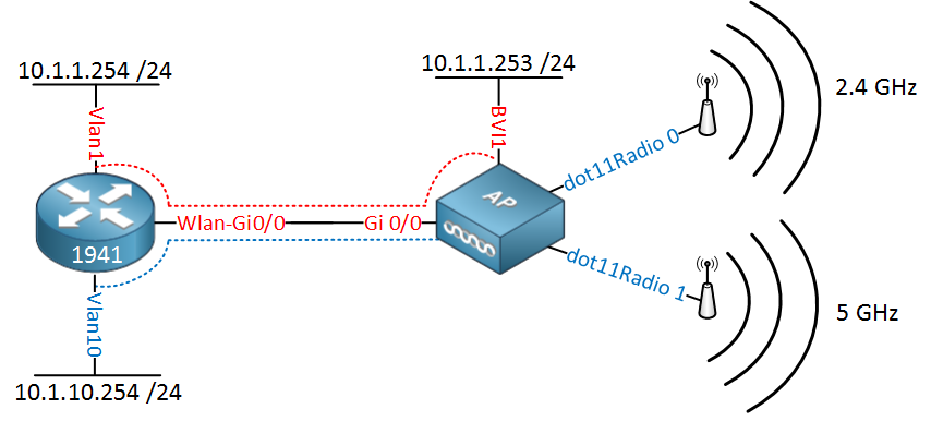
Let me explain this picture:
- On the router we will configure IP address 10.1.1.254 on the Vlan 1 interface and on the access point we have 10.1.1.253 on its BVI1 interface. This will be used for management traffic.
- The Vlan10 interface on the router will have IP address 10.1.10.254, this will be the default gateway for the wireless users.
First we will configure a DHCP pool for the wireless users:
Router(config)#ip dhcp pool VLAN10-WIFI
Router(dhcp-config)#network 10.1.10.0 255.255.255.0
Router(dhcp-config)#default-router 10.1.10.254
Router(dhcp-config)#dns-server 8.8.8.8Next step is to make sure the Wlan-Gi0/0 interface is operational:
Router(config)#interface Wlan-GigabitEthernet0/0
Router(config-if)#no shutdownRouter(config)#interface wlan-ap 0
The wlan-ap 0 interface is used for managing the embedded AP.
Please use the "service-module wlan-ap 0 session" command to console into the embedded AP
Router(config-if)#ip address 11.11.11.11 255.255.255.255Router(config)#interface wlan-gigabitEthernet 0/0
Router(config-if)#switchport mode trunkRouter(config)#interface vlan 1
Router(config-if)#ip address 10.1.1.254 255.255.255.0Router(config)#vlan 10
Router(config-vlan)#name WIFI
Router(config-vlan)#exitRouter(config)#interface vlan 10
Router(config-if)#ip address 10.1.10.254 255.255.255.0Router#service-module wlan-ap 0 session
Trying 1.1.1.1, 2067 ... Open
ap#ap#erase startup-config
Erasing the nvram filesystem will remove all configuration files! Continue? [confirm]
[OK]
Erase of nvram: completeap#reloadAp>enable
Password: Cisco
Ap#Ap(config-if)#interface gigabitEthernet 0
Ap(config-subif)#bridge-group 1Ap(config-if)#interface gigabitEthernet 0.10
Ap(config-subif)#encapsulation dot1Q 10
Ap(config-subif)#bridge-group 10Now we’ll configure the BVI interface for management traffic:
Ap(config)#bridge irb
Ap(config)#interface BVI 1
Ap(config-if)#ip address 10.1.1.253 255.255.255.0First we will create a simple wireless network that uses a pre-shared key for WPA:
Ap(config)#dot11 ssid WIFI-PSK
Ap(config-ssid)#authentication open
Ap(config-ssid)#authentication key-management wpa
Ap(config-ssid)#guest-mode
Ap(config-ssid)#wpa-psk ascii Cisco123- The name of the wireless network is “WIFI-PSK”.
- WPA Authentication.
- The name of the wireless network is broadcasted.
- The pre-shared key is “Cisco123″.
Ap(config)#interface dot11Radio 0
Ap(config-if)#description 2.4GHz Radio
Ap(config-if)#encryption mode ciphers aes-ccm
Ap(config-if)#ssid WIFI-PSK
Ap(config-if)#bridge-group 10
Ap(config-if)#no cdp enableAp(config)#interface dot11Radio 1
Ap(config-if)#description 5GHz Radio
Ap(config-if)#encryption mode ciphers aes-ccm
Ap(config-if)#ssid WIFI-PSK
Ap(config-if)#bridge-group 10
Ap(config-if)#no cdp enable
Don’t forget to create an access-list to
restrict traffic between the management and wireless VLANs. We seperated
them but there’s nothing stopping the router from routing between the
two vlans…
A pre-shared isn’t a very secure method so if you are interested,
here’s how you can configure your access point to use an external radius
server for WPA Enterprise:Ap(config)#aaa new-model
Ap(config)#aaa group server radius RADIUS_GROUP
Ap(config-sg-radius)#server-private 172.16.1.253 auth-port 1812 acct-port 1813 key Cisco123
Ap(config-sg-radius)#exit
Ap(config)#aaa authentication login RADIUS_LIST group RADIUS_GROUP
Ap(config)#aaa authorization exec default localAp(config)#dot11 ssid WIFI-RADIUS
Ap(config-ssid)#authentication open eap RADIUS_LIST
Ap(config-ssid)#authentication key-management wpa
Ap(config-ssid)#guest-modeAp(config)#interface dot11Radio 0
Ap(config-if)#no ssid WIFI-PSK
Ap(config-if)#ssid WIFI-RADIUS
do you know how to exit from ap console to enter router console?
RépondreSupprimerthanks for your help